
- #USB PIC PROGRAMMER CIRCUIT DIAGRAM PDF SERIAL#
- #USB PIC PROGRAMMER CIRCUIT DIAGRAM PDF PC#
- #USB PIC PROGRAMMER CIRCUIT DIAGRAM PDF SERIES#
The USB bus communication protocol is very complex so in this article we are going to touch only the basic principles, just enough to be able to use the USB bus. Power Distribution and New Connector Specifications SpecificationĬan work in conjunction with Power Delivery 2.0 USB Speeds and Specifications Specification Operates in USB 2.0 mode if plugged into a USB 2.0 A receptacleīuy a USB PIC Microcontroller from Our Online Shop Operates in USB 2.0 mode if plugged into a USB 3.0 Micro B receptacle. Operates in USB 2.0 mode if plugged into a USB 3.0 B receptacle Operates in USB 2.0 mode if plugged into a USB 3.0 A receptacle To reduce the size of the connector, there are USB-mini and USB-micro connectors. The A connector faces the Host while the B connector faces the device.

There are different types of USB connectors grouped into Host and device connectors. If these signals are not used in the alternate mode they may be eliminated

When used, a Hub will be considered one of the 127 Devices.Īll components of a USB system connect to each other using one of the USB specified cables and connectors. If more than one device is present one or more USB HUBs must be used. With a USB system, there is always a single USB HOST and USN devices connected to it from 1 to 127 USB Devices.
#USB PIC PROGRAMMER CIRCUIT DIAGRAM PDF PC#
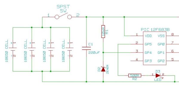
When a connection to a PC is required, the USB is the obvious choice!įigure 1: USB bus communication circuit diagram
#USB PIC PROGRAMMER CIRCUIT DIAGRAM PDF SERIAL#
Today USB has grown beyond PCs to become the common interface for many embedded industrial and consumer products like in cameras, GPS, printers, etc.Īlmost all PCs nowadays, especially portable ones no longer have a serial port (COM Port), it has been replaced by USB ports. Shortly after being introduced, USB ports quickly replaced the legacy connectors on most personal computers. The primary motivation was to allow peripherals to be automatically configured when they are plugged into a PC (often referred to as plug-and-play). The Universal Serial Bus or USB for short, was designed to replace the myriad of connectors found on Personal Computers (PCs) in the 1990s.
#USB PIC PROGRAMMER CIRCUIT DIAGRAM PDF SERIES#
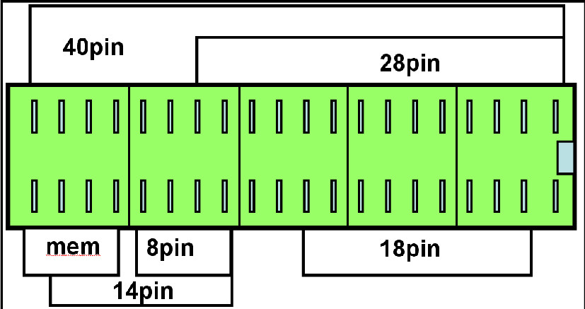
In 3.3V expansion (LVICP) board a 5V to 3.3V,a voltage regulator such as LM1117 or similar is need.įig 5 and Fig 6 shows the expansion boards and circuit diagram for different series of microcontrollers. For different series of microcontrollers, different expansion board is used. I made the expansion board using perf board. It gives the advantage of easy to program the microcontroller to the user.Įxpansion board can be easily made using the perf board or in breadboard, because it is very simple circuit. The different series of microcontroller is having different pin and configuration for programming. Expansion board interfaces the programmer with the microcontroller.


 0 kommentar(er)
